
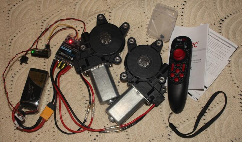
I've been doing background tinkering on a potential low cost 3d printed, remote controlled tracked vehicle project, and to be frank it hasn't been going spectacularly until today — when I finally got a working powertrain assembled. To be clear this so far includes literally none of the track equipment, but I can just borrow that from someone else's project if I want to, and I probably will. This covers the other half of the equation, how to make the thing go.
I am not in fact attempting to make a tank, although the project will somewhat resemble one as I'm planning to run the tracks completely around in a circuit like on the very first tanks. The machine isn't going to be going fast enough to throw material attached to the tracks into the air, and this keeps the design simpler. I'm building a non-turreted roof and underfloor inspection system, which I hope to also make capable of performing some simple mechanical tasks. It's not going to be shooting anything but pictures.
I have it in mind to make it possible to build this project at a variety of different strengths for different purposes, and therefore out of different materials and even using totally different assembly strategies, but all based on the same basic suspension design and using the same sort of powertrain. An advantage of a tracked vehicle design is that the tracks are driven from one end, so while the total complexity is somewhat higher (tracks are made out of a number of links, which themselves are made from at least two parts but which can be much more complicated) the drive system itself can be reasonably simple.
It doesn't get much simpler than the system design I'm using here, which involves cheapest-possible commodity window motors and an RC speed controller. I'll also be including some self-resetting thermal circuit breakers to try to protect the Electronic Speed Controller. These are probably mostly just additional potential points of failure and I might delete them again later if they are problematic, but I don't want to rely only on the ESC's internal protections. From my research (based on absolutely no testing, but including empirical evidence in the form of fuse ratings) in normal use window motors draw less than 15 amps even when getting stalled out at the end of travel, and I'm using an allegedly 30 amp per motor ESC, so this will hopefully be no problem anyway. Still, safety first.
In fact, I started first with a supposedly (dual) 50 amp ESC. It arrived refusing to function, with only the BEC1 showing signs of life. That died as soon as I tried to run a servo, even with no load. I was using it just to test the signal coming from the radio to verify that it was working. This time I had no problems, I just plugged everything in and it worked fine. I presume most of the time the other ESC works OK and I just got a bad unit, but I decided to switch to a different one anyway.
OK, so what did I plug in, and why that thing? This system is primarily based on the following major components:
- HOTRC DS-650 6CH 2.4G Radio System
This one-hand-operation radio transmitter/receiver set is ideal for this kind of project and also ludicrously cheap at $21.50 (sale price) including the 6 channel receiver. This is a bidirectional 2.4 GHz RC system which reports back battery voltage measured using the included signal wire, intended to be connected to the balance charge connector but which can also be hardwired in anywhere to report any voltage as it uses a high-impedance sensor with a ground reference wire. HotRC sells three of these one-handed units; this is the middle model of the three. This has too much functionality to cover here, but it's got a color screen and a lot of interesting functionality including cruise control. This does include mixing including a tank mode, but I decided there wasn't really any benefit to using that over what's in the ESC: - KingModel 30Ax2 Bidirectional Brushed Speed Controller
Available in capacities anywhere from 10A up to 60A, these speed controllers are again ideal for this kind of project. Easily configured through the use of two jumpers at the edge of the PCB which toggle brake and mixed input mode, these are easy to use without programming but also potentially fully reprogrammable and expandable as they provide serial communication test points on the bottom of the board. With my motors I couldn't detect any difference so far between having the brake enabled or not, and I don't really expect to. I am not building a performance vehicle, so it shouldn't matter that I used motors which cannot coast: - Universal Model 4 Holes 8 Teeth Electric Window Lift Motor
I have no idea what vehicle[s] these window motors fit, I only know that they were not priced with $65 shipping when I bought them. You can see some other similar motors linked below them in their listing. The big advantage of using these motors is that they have a worm drive, which is extremely powerful. Unfortunately, it does prevent them from being able to coast, and as the motor parts of the window motor assemblies have no inertia to speak of, they stop with something of a halt when power is removed. This is useful in their mission as a power window motor, but a slight detriment here as it may make fine positioning difficult when driving with the joystick. It's also a benefit as it produces all of the gear reduction I need. Worm drives are not very efficient, especially at high speeds, but I will not be needing high speeds.
This is literally everything needed besides connector plugs and the like to get two steeply geared motors working as you would need them to work for a tracked vehicle with full mobility. That is, if you apply accelerator input the motors run in opposite directions, if you apply only steering input then they run in the same direction, and if you steer while applying acceleration then the motor on the side you're steering towards is stopped to make the vehicle pivot around that track while the other motor continues to run at proportional speed. This is not an agile control scheme, and for a more sporty vehicle I would probably consider looking into using the mixing mode on the controller so that you can slow the inside track instead of stopping it.
As far as power, I already have a pair of Zippy 4S 5200 mAh LiPos which should allow a vehicle like this to run a lot longer than I want to operate it. I am still investigating what type of PDB I would like to use to connect the batteries to the ESC. I have fantasies of using an embedded MCU and latching relays to provide a power control system which can detect battery failure and cut out the bad pack, but in this vehicle I plan to settle for an XT60 connector bus bar with some sort of attachment I can run out to a drone PDB to provide other voltages for camera and video TX, and to supply power to other motors or controllers which operate accessories. For testing of the rig I used the smaller Tattu drone pack shown in the photo.
4S voltage (fully charged around 16.8) is close enough to 12 volts to where you don't much risk burning out the brushes2 with arcing they aren't designed for, but even if it should occur, part of the appeal of using window motors is that they're cheap. They also come in a lot of shapes and sizes which you could integrate into different designs, and just as importantly as any of these things are also very flat so they package into doors more easily. This also makes them easy to package into your vehicle while leaving a lot of room behind. Finally, they feature a gear drive which makes them easy to adapt into your projects; you can simply model a negative of the shape into a piece which fits over the gear, or you can create your own gear. I imagine using the former approach, and also including a TPU damper bushing to absorb shocks between the tracks and motor, thereby hopefully avoiding the need to shock mount the motor as well.
This is early stages so there aren't a lot of things to know, but one thing you should know is that most brushed ESCs in this class seem to be old designs which don't understand a digital servo signal. These have more communications cycles per second and can react more quickly, but that really isn't relevant here. The ESC I bought gave an explicit warning about this. It is not an issue with this transmitter, which is configured to the slower refresh rate by default, but it's worth mentioning.
I've alluded to the other thing you need to know about this design above, which is that it is utterly unsuited to going fast. This design is based around two primary concepts, low cost and high payload capacity, with an honorable mention for terrain handling capability. I plan to use bent torsion bar suspension for similar reasons to the other decisions, namely low cost and minimal impact on interior volume. There are some very interesting 3d printed tank designs out there which are meant for maximum speed, and they make entirely different design decisions as a result.
Offtopic endnote: Along the way I sort-of-fixed a problem with inserting Drupal Media images into comments using ckeditor5, which I mentioned back in April in an article about resuming a failed 3d print. Of course I had a whole lot of help in the form of basically the whole fix, and I only did a hacky little temporary patch to get it to produce some kind of useful information on Drupal 11.4.6 which I've just updated to. I was getting only an error, but the tweak I've done linked above makes it so that inserting Media objects (or images at least, I've tested nothing else) works correctly.
- 1
Battery Eliminator Circuitry, AKA the power supply for the servo and receiver which is built into the speed control. Before it existed, RC radios were powered by battery packs separate from the one which ran the motor, which was commonly not electric anyway.
- 2
But undervolting the motors under load does risk causing harm because of ohm's law, which does apply to inductive loads like motors which can be stalled.